


Storz System Couplings and Hoses
Storz System hose couplings are often referred to as fire brigade couplings.
They are symmetrical, non-shut-off couplings.
The couplings are connected by inserting the lug parts into each other and twisting them against each other.
The connection fittings to be coupled are identical on the coupling side and can be connected in any way, provided they are the same size.
Application area:
for industry, fire brigade, refineries, agriculture, construction, shipping, military, and disaster control
Application:
- for closing couplings of the appropriate size
- Quick connection and disconnection with a 120° turn
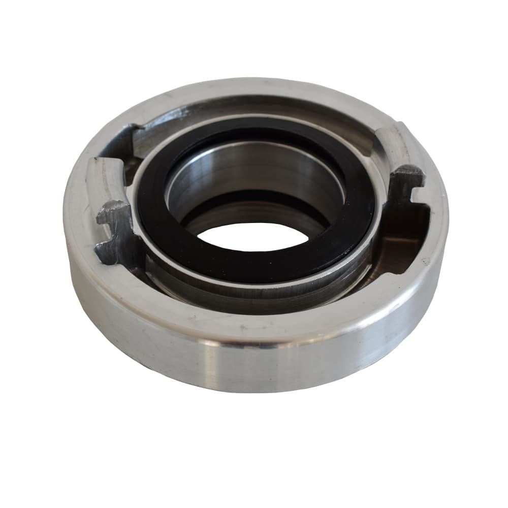
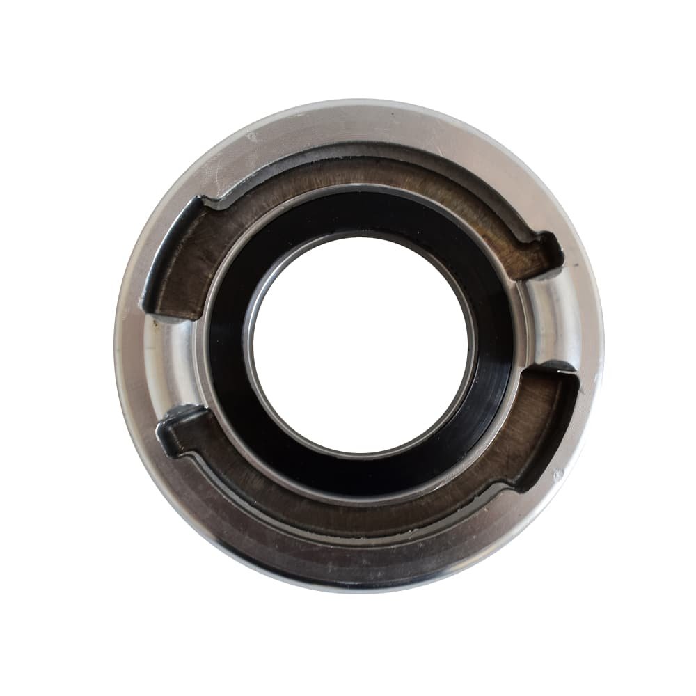
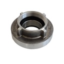
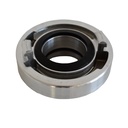
Suction coupling:
Suction couplings are used for connecting suction hoses.
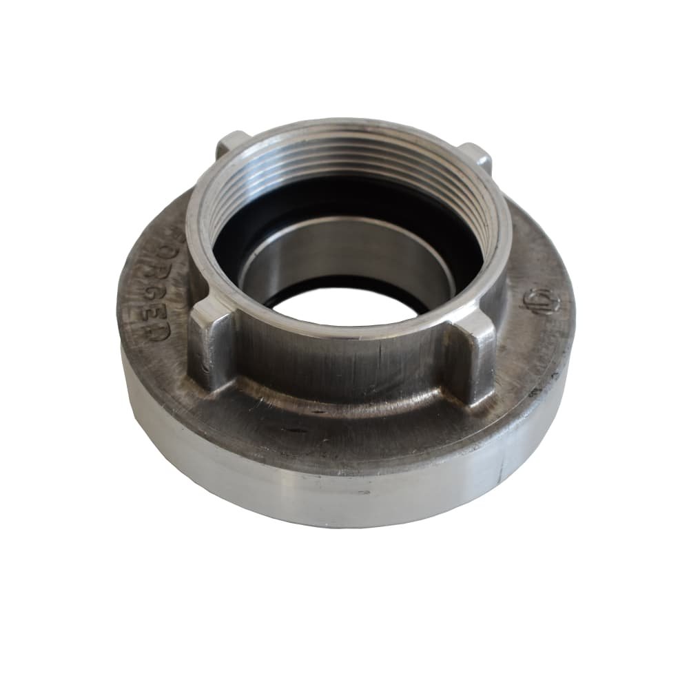
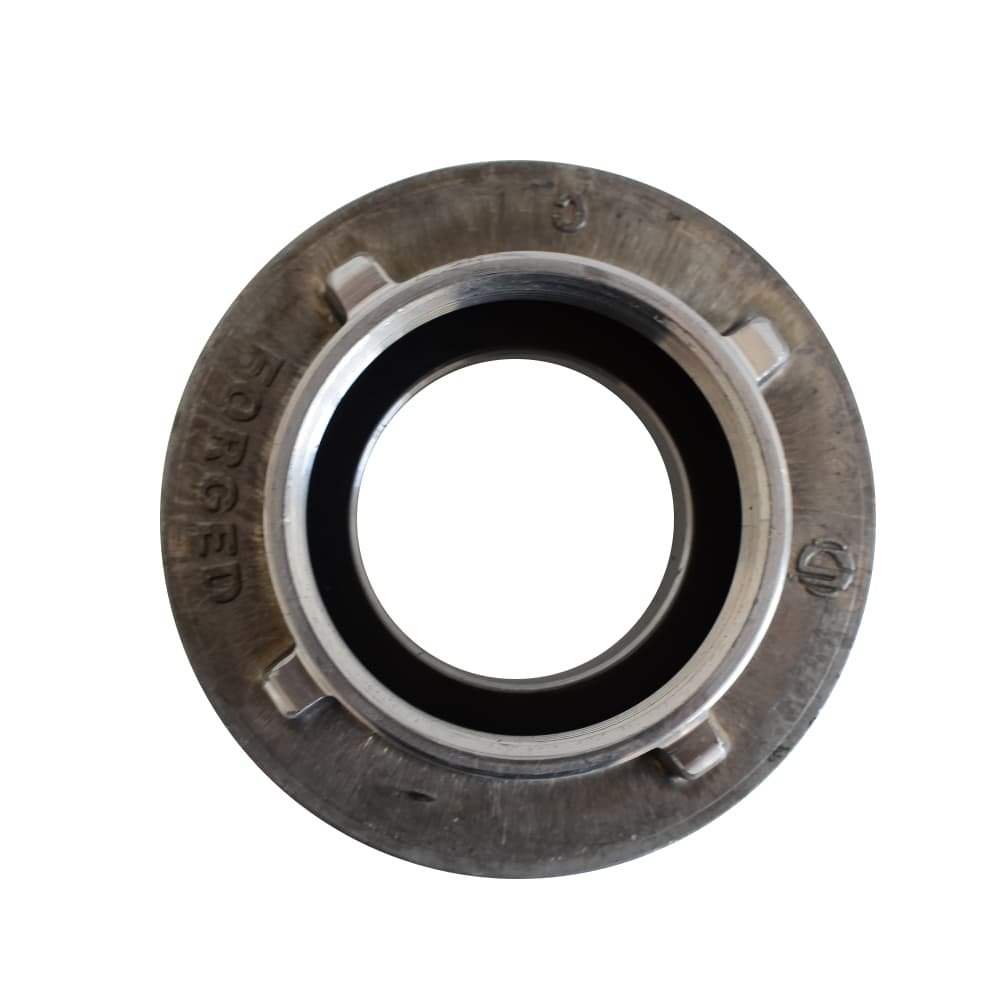
Fixed coupling:
Fixed couplings (threaded pieces in many variants) are used for connecting hoses to fittings. They are screwed on one side with a pipe thread on a water-carrying fitting or a hydrant. On the other side, the usual couplings of a pressure hose or a suction hose can be connected.
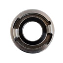
Blind coupling:
Blind couplings (i.e., end caps for temporarily unused Storz connections) are used as an end on fittings to protect them (e.g., against the ingress of dirt into pumps) and must not be pressurized if the line cannot be relieved (risk of accident when loosening the blind cap under pressure).
Coupling wrench made of steel for Storz sizes A/B/C
- Material: Steel
- for Storz sizes A/B/C
- with cold protection
Construction and industrial hose A/102, B/75, C/52, D/25 in various lengths:
Color: outer white
Material: Outer: polyester yarn, round woven, warp 2-ply twisted
Operating pressure: 10 bar
- with Storz suction couplings
- Wire binding
- uncoated
- Protective sleeve to prevent chafing at the hose coupling
User information:
This operating manual must be read carefully before first use and observed during use.
1. General information on flat or pressure hoses
Pressure hoses have the primary task of liquid transfer, especially water.
However, they can also be used for draining wastewater or similar. They consist of round-woven plastic fibers (in this case polyester) and are coated inside.
A significant advantage of flat hoses is their low weight and flexibility, which makes them easy to fold and transport when not pressurized.
2. During use
Due to their primary task and predominant areas of use, flat hoses are subject to high external influences that can shorten their lifespan.
For optimal service life, the following is recommended:
- Do not exceed the maximum operating pressure.
- When laying out the hoses, ensure that they are rolled out (if possible). Otherwise, always pull flat. This can prevent the hose from dragging on the edge on the ground and immediately damaging the hose cover.
- Avoid rough surfaces if possible.
- Do not drag hoses over sharp-edged, pointed objects and/or surfaces.
- Never drop hose ends or fittings, as this can lead to damage to the lugs or the fittings themselves.
- Do not pull or drag pressurized hoses on the ground, as the resulting abrasion can damage the hose cover. Vibrations of pressurized hoses can be reduced or absorbed using accessories. For example, with burlap, tarpaulins, or bandages.
- If hoses are to be used at transitions, hose bridges should be used. Hoses should never be driven over or stepped on.
- Keep hoses (if possible) away from acids, chemicals, and hazardous substances.
3. After use:
To ensure the longevity of the hoses, the following instructions should be observed after use:
- To remove the remaining amounts of the liquid medium from the hose, the hose should be lifted over the shoulder. Never step on the hose!
- After use, free hoses from deposits inside the hose (sand, etc.), i.e., rinse them out. They should then be dried (otherwise mold/lime can deposit inside the hose, which can permanently damage the core).
- Clean the hose cover from external dirt.
- Hoses must never be stored in a damp condition.
- Check fittings for integrity.
- Store hoses (if possible) in a rolled-up condition.
- When rolling up, ensure that the hoses do not drag on rough surfaces as when unrolling.
|
Article |
Connection |
Material |
Dimension |
Lug Distance |
Working Pressure |
|
D Coupling with Spigot |
Suction coupling with hose spigot |
Aluminum |
25 mm |
31 KA |
15 bar |
|
C Coupling with Spigot |
Suction coupling with hose spigot |
Aluminum |
50 mm |
66 KA |
15 bar |
|
B Coupling with Spigot |
Suction coupling with hose spigot |
Aluminum |
75 mm |
89 KA |
15 bar |
|
D Coupling with 3/4" IG |
Fixed coupling with internal thread |
Aluminum |
3/4 inch |
31 KA |
15 bar |
|
D Coupling with 1" IG |
Fixed coupling with internal thread |
Aluminum |
1 inch |
31 KA |
15 bar |
|
C Coupling with 1" IG |
Fixed coupling with internal thread |
Aluminum |
1 inch |
66 KA |
15 bar |
|
C Coupling with 1 1/4" IG |
Fixed coupling with internal thread |
Aluminum |
1 1/4 inch |
66 KA |
15 bar |
|
C Coupling with 1 1/2" IG |
Fixed coupling with internal thread |
Aluminum |
1 1/2 inch |
66 KA |
15 bar |
|
C Coupling with 2" IG |
Fixed coupling with internal thread |
Aluminum |
2 inch |
66 KA |
15 bar |
|
B Coupling with 2" IG |
Fixed coupling with internal thread |
Aluminum |
2 inch |
89 KA |
15 bar |
|
B Coupling with 2 1/2" IG |
Fixed coupling with internal thread |
Aluminum |
2 1/2 inch |
89 KA |
15 bar |
|
B Coupling with 3" IG |
Fixed coupling with internal thread |
Aluminum |
3 inch |
89 KA |
15 bar |
|
D Coupling with 1" AG |
Fixed coupling with external thread |
Aluminum |
1 inch |
31 KA |
15 bar |
|
C Coupling with 1" AG |
Fixed coupling with external thread |
Aluminum |
1 inch |
66 KA |
15 bar |
|
C Coupling with 1 1/4" AG |
Fixed coupling with external thread |
Aluminum |
1 1/4 inch |
66 KA |
15 bar |
|
C Coupling with 1 1/2" AG |
Fixed coupling with external thread |
Aluminum |
1 1/2 inch |
66 KA |
15 bar |
|
C Coupling with 2" AG |
Fixed coupling with external thread |
Aluminum |
2 inch |
66 KA |
15 bar |
|
B Coupling with 2" AG |
Fixed coupling with external thread |
Aluminum |
2 inch |
89 KA |
15 bar |
|
B Coupling with 2 1/2" AG |
Fixed coupling with external thread |
Aluminum |
2 1/2 inch |
89 KA |
15 bar |
|
B Coupling with 3" AG |
Fixed coupling with external thread |
Aluminum |
3 inch |
89 KA |
15 bar |
|
D Blind coupling |
Blind coupling with chain |
Aluminum |
- |
31 KA |
15 bar |
|
C Blind coupling |
Blind coupling with chain |
Aluminum |
- |
66 KA |
15 bar |
|
B Blind coupling |
Blind coupling with chain |
Aluminum |
- |
89 KA |
15 bar |
|
Reduction C-D |
Transition piece from C to D |
Aluminum |
- |
66 KA to 31 KA |
15 bar |
|
Reduction B-C |
Transition piece from B to C |
Aluminum |
- |
89 KA to 66 KA |
15 bar |
|
Reduction A-B |
Transition piece from A to B |
Aluminum |
- |
133 KA to 89 KA |
15 bar |
|
D Nozzle |
Nozzle type 25D |
Aluminum |
2 inch1 inch |
31 KA |
- |
|
C Nozzle |
Nozzle type 52C |
Aluminum |
2 inch |
66 KA |
- |
|
D Gasket |
Gasket type Storz |
NBR |
31 KA |
- |
|
|
C Gasket |
Gasket type Storz |
NBR |
66 KA |
- |
|
|
B Gasket |
Gasket type Storz |
NBR |
89 KA |
- |
|
|
A Gasket |
Gasket type Storz |
NBR |
133 KA |
- |
|
Thread sizes conversion inch to mm (mm in approx. indication) |
|
|
1/4 inch |
12.5 mm |
|
3/8 inch |
16 mm |
|
1/2 inch |
19 mm |
|
3/4 inch |
26 mm |
|
1 inch |
32 mm |
|
1 1/4 inch |
40 mm |
|
1 1/2 inch |
48 mm |
|
2 inch |
59 mm |
Note: May show small scratches or streaks due to production!
